Introduction:
Induction hardening is a case hardening process that improves the wear resistance, surface hardness, and fatigue strength of parts under dynamic and/or thermal stresses by creating a hardened surface layer while maintaining the unaffected softcore. This hardened layer, in part, is an essential quality characteristic of the induction hardening process. However, to evaluate the hardening process’s quality, the destructive testing method is typically used, which is very time-consuming and expensive. In industry, besides inspection of surface hardness, induction Case-depth measurement is one of the essential parameters for monitoring the quality of Induction hardened steel products. First, the case depth is typically measured by sectioning, polishing, and etching the workpiece to reveal the depth of the hardened layer. Then, the sample is tested at a hardness testing machine for the required hardness, generally HRC 50. After the sample finds an area that meets the required hardness, the distance from the surface to the hardness indent is measured using a Brinell scope for effective case depth measurements.
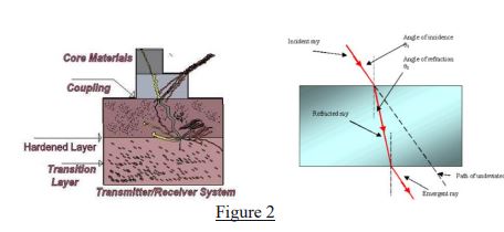
Instead of destructive inspection, non-destructive technology is available that performs case depth measurement, saves hours of typical inspection work, and is done without destroying the part. The Ultrasonic non-destructive inspection technique is based on the propagation of ultrasonic shear waves to the test part. The shear waves are emitted into the specimen by keeping the probe at a specified angle. When the ultrasonic signal reaches the part surface, due to the surface roughness and velocity differences, some sound waves get reflected in multiple directions. Furthermore, some sound waves propagate through the part as a shear wave, see figure 2.

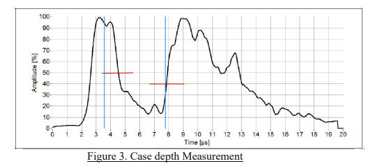
The ultrasonic probe for inspection must be inclined at a specified angle to generate the shear waves into the specimen. During the inspection, the probe’s first ultrasonic echo occurs due to the backscatter from a metal surface. After that, the remaining ultrasonic energy enters the hardened layer of the metal. The hardened layer is made of fine-grain martensitic microstructure, and thus, no scatter of ultrasonic wave takes place in this region. However, when the shear wave reaches the transient zone (TZ), where the martensitic structure is gradually converted to the ferrite-pearlite structure, which is of larger grain size, once again, energy is scattered at grain boundaries, and some of the energy backscatter and form the second echo. The difference in time-of-flight (ToF) of these two echoes is proportional to the case depth of the specimen. Figure 2 shows a probe riding on the part with an ultrasonic signal returning from the surface and the transition zone. This shows a typical ultrasonic response from a induction hardened steel axle shaft. The two gates, designated by horizontal lines set at the equipment display screen, measure the distance between the two points at which the echoes cross a value. For example, fig. 3 below shows that the front surface gate is set at 50%, the transition gate is set at 40% of the full-screen height, and the signal distance between the two is measured as a case depth.

To obtain a reliable UT signal, a few conditions must be satisfied. First, the hardening must be deep enough to sufficiently separate the front surface and backscattered peaks in time. This assures distinct peaks from which time-of-flight can be calculated. Second, the transition zone between the case and core must be sufficiently discrete such that the backscattered peak is above noise levels. A good response is achieved by induction hardening a component with an unhardened core, where the minimum hardening depth is between 1.5 and 2 mm. In this instance, the fine-grained martensitic case zone is in sharp contrast to the coarse-grained ferrite/pearlite microstructure of the core. This condition results in a distinct backscattered signal peak. Surface treating processes unsuitable for ultrasonic measurement methods include shallow hardening processes such as nitriding, diffusion hardening processes such as carburizing, and relatively slow conductive surface heating processes that produce a broad transition zone.
Conclusion:
Nondestructive case depth measurement has enabled significant cost reductions by reducing or eliminating destructive analysis. This is especially true for large and complex parts where destructive sampling is prohibitive. However, successful nondestructive inspection applications are contingent on understanding the details of the material’s condition as well as the limitations of the test method.

